
Retrofitting Concept and Demonstrator for Drying and Moisture Measurement Systems with an Industry 4.0 Gateway
Hanover / Lemgo In pneumatic systems, air leaks can occur at the executing and connecting components, leading to high energy losses. This results in unplanned downtimes, which are associated with high costs. Ad-hoc leaks can be detected directly by the specialist staff, but creeping leaks are either detected late or not at all. Conventional inspection requires costly measuring instruments and appropriately trained specialists, so it is usually carried out (too) rarely or not at all. Not only can maintenance costs be reduced and unplanned downtimes reduced by early detection, but also by the most accurate location of such leaks.
As one of the world’s leading manufacturers of pneumatic compressed air valves, Aventics GmbH, which belongs to the Emerson Group, together with the AI Community OWL and the KI Reallabor, organized a hackathon on the topic of automatic leakage localization on the weekend of November 27-29, 2020. Here, AIM Agile IT Management GmbH was able to successfully apply a Smart Machines AI method developed by it and thus prevail against the competition.
From virtual hackathon to real plant
Building on this, a cooperation project was launched, the primary objective of which is to make the process usable under real conditions. While the data from the hackathon came from a test system operated under laboratory conditions, in this case it is used on a demonstration system in the SmartFactoryOWL’s real laboratory, which works analogously to industrial production operations. This is precisely the objective of the test setup in the SmartFactoryOWL: Here, processes related to Industry 4.0 can be developed, researched and tested by companies. As part of the cooperation between the Emerson Group, the Fraunhofer Institute for Industrial Automation IOSB-INA and AIM Agile IT Management GmbH, a test project was carried out to detect and locate leaks in pneumatic systems.
Detection and Localization of Leaks
The objective for the AI-based method is to learn the relationship between control signals of the cylinders and the measured value for the compressed air flow rate for a given operating program. Subsequently, the expected flow rate can be predicted with the algorithm. The analysis of the resulting prediction error finally enables the detection and localization of any leaks. In addition to assigning leaks to one of the cylinders, the method also allows statements to be made about the cylinder side (rod/piston) on which the leak is present.
Accordingly, the following applies: The more precisely the algorithm can predict the flow rate in the compressed air system, the earlier and more robustly a detection and location of leaks can take place on the basis of statistical deviations of the prediction error.
Challenges / Task
The configurations of customer systems are very individual and consist of a few to several hundred components. The physical properties (e.g. viscosity of the air) and framework conditions (e.g. operating temperature) do not allow simple linear models of the overall system. Often, only a few data are available in customer systems, as they are already older or the costs of the sensors are high in relation to other components. Thus, only the central flow rate and the control data of the system are available. In order for a solution to be suitable for practical use, no training data can be provided for the actual leaks – but only the current reference behavior of a system.
This results in the following core challenges from the perspective of a procedure suitable for practical use:
- Few signals: due to missing sensors
- Heterogeneity: individual configurations and conditions of customer systems
- Complexity: few to several hundred components
- Limited training data: only reference behavior
- Non-linear behavior: physical properties (e.g. viscosity of the air)
- Localization: Wear must be assigned to the components
In particular, the last point is demanding, since the information regarding the affected component(s) is “hidden” in the dynamics of the signals.

Figure: Diagram of a pneumatic system
Project progress and solution
Based on previous experience, the partners were able to narrow down initial solution ideas early on. Blind Source Separation, for example, to separate the individual flows (source signals) from the mixed total flow, was out of the question due to the minimal information situation. The second – successful – approach was to learn the reference behavior of the system instead of concrete wear locations. If slight deviations from the expected behavior occur, they are detected early by the system and assigned to the causing component.
It is important for predictive maintenance solutions to understand the technical process and to use the corresponding domain knowledge. The partners jointly developed this expertise on the basis of the test setup. The test system has three stopper cylinders along a conveyor belt, which control the passage of workpieces through the system. A fourth cylinder is used to lift the workpieces along a lifting axis into a safety chamber for automatic processing by a laser and lowered again after the processing process. The entire passage of a workpiece through the system takes about one minute.
An AES control unit takes over the pneumatic control of the cylinders. Via another, IIoT-capable AES unit, leaks can be selectively specified remotely on individual cylinders and thus simulated. The entire compressed air system is monitored by a centrally positioned AF2 unit, which records the flow rate, temperature and pressure of the system.
The OPC UA protocol is used for the communication of the control and sensor signals between the control unit and the process, and the generated data is aggregated in an InfluxDB.

Figure: Setup of laboratory experiment
The starting signal was given. In short agile sprints, AIM proceeded step by step in close coordination with the Emerson team. One of the recipes for success is to start each solution development with a Data Quick Check – here, for example, the periodicities of the control, latencies and synchronicity of the control signals as well as general conspicuous features in the measurement series, such as dropouts or outliers, are analyzed and visualized. Already with the first analysis results, exciting insights and discussions about the technical process and signal transmission have arisen, e.g. about information losses due to small phase shifts, the period ratios of the switching frequencies and identified fluctuations and shifts of the time stamps.
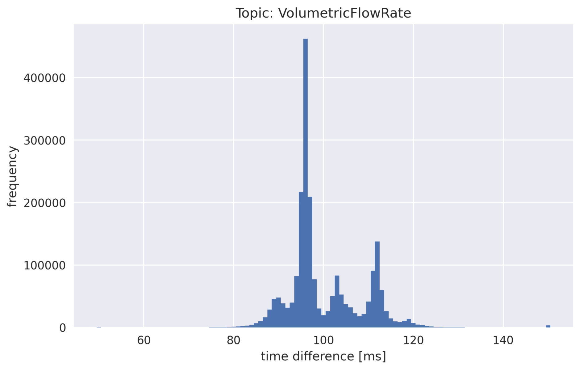
With this knowledge, the development of the method, which seemed promising, continued: A prediction model for the central total flow of the system is trained only on the basis of the control signals. The decisive trick here is not only to use the binary control data, but to make the system dynamics more easily accessible to the model by generating additional information. The relatively simple model achieves a prediction accuracy of over 90%. However, this is actually not the decisive factor, but only serves to determine a statistically significant prediction error when creeping leaks change the system behavior.

Figure: Prediction of air flow: Prediction error < 10%
In order to ultimately locate the leakage, further analysis steps and a significance test are carried out. This is done on a rolling basis over configurable time windows, so that a sequence of test results is created – in the following example, the assignment of the leakage is clearly visible (continuous red marking).

Figure: Statistical significance of the assigned deviations over time
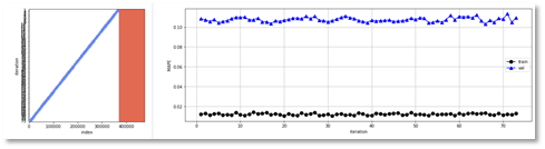
Of course, the amount of data or data sparseness is also an essential aspect: Deviations are detected and localized already on the basis of a short training period (calibration) and within a few minutes of the forecast (monitoring). In order to achieve this, we analyze the effect of different calibration periods on the performance on the one hand and the growing distance to the monitoring on the stability on the other hand:
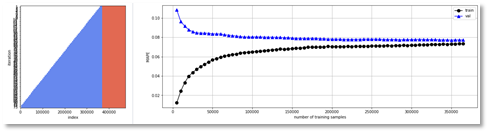
Figure: Analysis of the calibration periods
This solution is a good example of the fact that it is not the “brute force” application of AI, which is often propagated in the course of the hype e.g. around deep learning, that leads to success, but the combination of domain knowledge, classical methods and simple machine learning models can be much more effective.
Previous results and outlook
An integrated overall solution has already been developed in the Proof of Concept and in the subsequent MVP (Minimum Viable Product): The pneumatic system communicates with the AI-based method via MQTT (or via a database) and is fully automatically trained in “Calibrate” mode. The “Monitor” mode monitors the system and continuously sends a leakage status to all components.
On this basis, the integration into PLC or monitoring solutions can be easily carried out.

Figure: Integrated overall solution
In further steps, the degree of complexity will now be continuously expanded in order to test, for example, different process programs, components and connections – and to continuously improve and expand the process.
The aim is to cover as many customer situations as possible in the future and to use the method in 2021 with the first pilot customers of Emerson.
Cooperation with strong partners
Thanks to the good cooperation of all participants despite the Corona-related virtual communication channels, rapid progress could be achieved. After the busy planning phase, the system has been prepared by Fraunhofer IOSB-INA in cooperation with Emerson and AIM for the first test series. The still missing hardware components could be quickly organized by Emerson and already installed on site at the plant by the Fraunhofer Institute.
The AIM team is very pleased to be able to contribute knowledge and experience in the industrial AI application in this cooperation: “The innovative interaction between component/machine manufacturers, practice-oriented research and AI/ML experts practiced here is, in our view, a very important success factor. We hope to take an important step towards a predictive maintenance solution for the fully automatic detection and location of leaks in pneumatic systems in a broad industrial application landscape from the cooperation with these top-class partners. We are therefore eagerly awaiting the first results.”